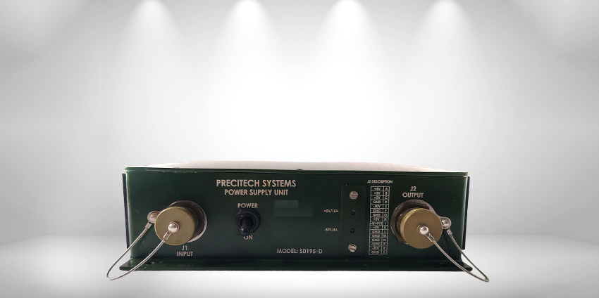
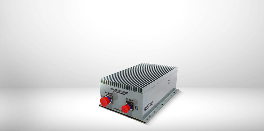
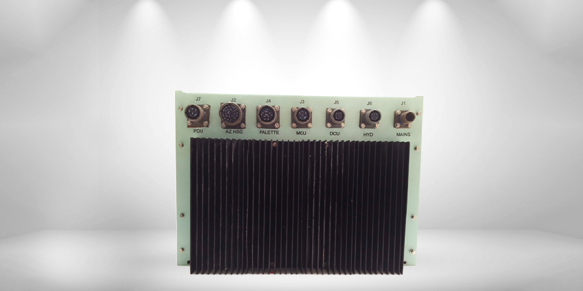
24V 60A DC PSU
- Home
- Power Electronics
- 24V 60A DC PSU
24V 60A DC PSU
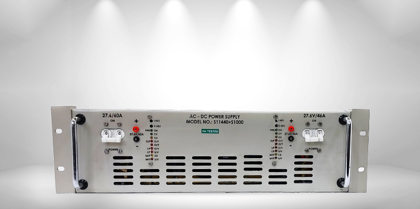
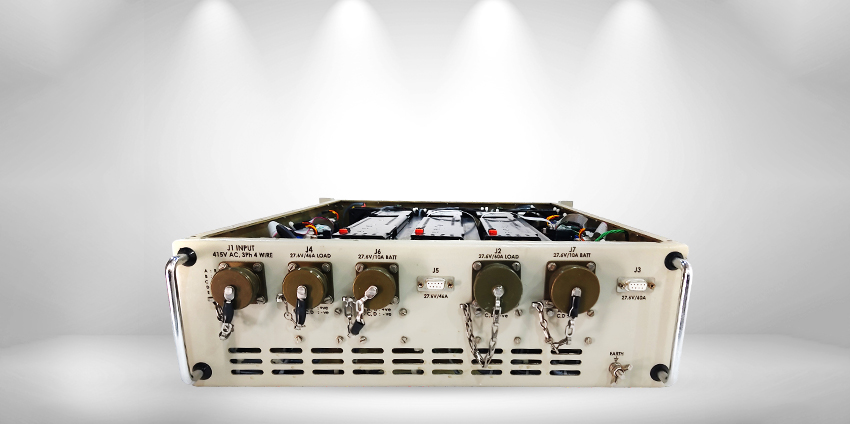
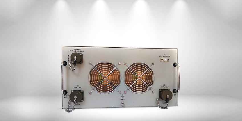
- INPUT: 3 Phase AC 415V, 3 Ph 4 Wire
- OUTPUT: 27.6VDC 60A and 27.6VDC 46A each rectifier with battery charging feature
- REDUNDANCY: 3KW � 2 rectifiers in dual redundancy mode (hot swappable)
- DIMENSIONS: 4U 19� rack configuration
Environmental Specifications (Rugged Environment)
- Operating Temperature: -10�C to +55�C
- Storage Temperature: -20�C to +65�C
- Relative Humidity: 20�90% RH (Non-condensing)
- Cooling: Internal force-air cooled (front to rear)
EMI/EMC Specifications
- Electrical: GB4943-2001, IEC 60950-1, UL60950-1
- EMI: EN 55032:2015, EN 55035:2017, EN61000-3-2:2014, EN55022 Class-A
- ESD: GB17626.2-1998 / IEC61000-4-2
- EFT: GB17626.4-1998 / IEC61000-4-4
- SURGE: GB17626.5-1998 / IEC61000-4-5
- DIP: GB17626.11-1998 / IEC61000-4-11
- Conducted Immunity: IEC61000-4-6
- Radiated Immunity: IEC61000-4-3
- Environment: ETSI EN 300 019-2, ETSI EN 300 132-2
Main Features
- Wide operating range of AC input voltage
- Real-time detection of power system status
- Hot-swappable rectifier modules
- Input over/under voltage protection
- Output over voltage protection
- Output over current protection
- Rugged connectors for error-free interconnection
- Battery charging facility
- Battery under-voltage cut-off (prevent deep discharge)
- Operator-friendly real-time indicators for faults, status, voltage & current
- When batteries are fully charged, full 60A & 46A available for load
Brief Description
Each rectifier provides rated current of 60A (50A load + 10A battery charging) at 27.6V, and 46A (36A load + 10A battery charging) at 27.6V. Two rectifiers operate in N+1 redundancy mode with 415VAC 3-phase UPS input. If one rectifier fails, the other continues supplying the full rated 60A and 46A. Faulty rectifier modules auto-isolate and are hot-swappable without shutting down the system. Input and output distribution is handled through a Distribution Box, with redundant diode paralleling of the rectifiers.
Technical Specifications
| S/L | Parameter | Specification |
|---|---|---|
| 1 | Input Voltage | 415 VAC �10%, 3 Ph, 4 Wire, 45�65 Hz |
| 2 | Input Current | < 5A per phase |
| 3 | Output |
1. 27.6VDC / 60A (50A Load + 10A Battery Charge) 2. 27.6VDC / 46A (36A Load + 10A Battery Charge) |
| 4 | Line & Load Regulation | 0.5% (120mV) measured at output connector pins |
| 5 | Protection (per output) |
AC Input undervoltage AC Input overvoltage Output overvoltage Output overload Short circuit |
| 6 | Ripple | <300mV p-p (Measured with 0.1uF disc + 100uF electrolytic in parallel, 20MHz BW) |
| 7 | Indications (per output) |
PWR ON � Green CV � Green CC � Orange Output O/V � Red O/T � Red AC Input Overvoltage � Red AC Input Undervoltage � Red Battery Charging � Yellow Battery UV Cut-off � Red |
| 8 | Earthing | Provided |
| 9 | M&C Functions |
Status of voltages & currents Power supply fault status |
| 10 | Connectors |
MS3102R-18-11P (J1) � Input MS3102R-22-22S (J2) � Output 27.6V/50A MS3102R-22-22P (J6) � Battery Charging Output 27.6V/10A 9-Pin D-Connector Female (J3) � M&C 50A MS3102R-18-10S (J4) � Output 27.6V/36A MS3102R-18-10P (J7) � Battery Charging 27.6V/10A 9-Pin D-Connector Female (J5) � M&C 36A |
| 11 | Controls (per output) |
Output ON/OFF MCB on front panel Test points for outputs I-ADJ and V-ADJ recessed potentiometers |